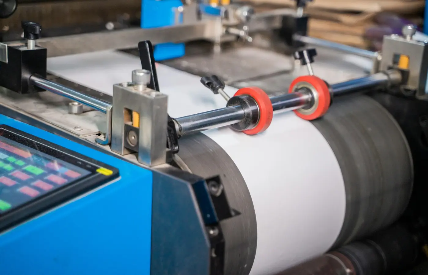


Label matrix breaks occur when the force needed to strip and rewind the waste web exceeds the strength of that remaining web. The matrix is not simply scrap: after die-cutting, it is a narrow, interrupted web of facestock that must separate from labels, pass through a strip path, and wind reliably under controlled tension.
A break can therefore originate in the die-cut, the artwork and waste geometry, the pressure-sensitive construction, the stripping route, or the winding conditions. Repeated failures are best treated as a system diagnosis rather than as a reason to increase die pressure or web tension immediately. Changing several settings at once may restore production temporarily while concealing the condition that caused the break.
Record where and when the matrix fails before making an adjustment. The break pattern often provides a more useful starting point than the break itself.
Read the break pattern before changing settings
The location, repeatability, and timing of a matrix break can narrow the investigation. A break in the same position on every label repeat is different from a break that appears after a speed increase or only near the end of a roll.
A troubleshooting guide from All In Label identifies the relationship between stripping force and the strength of the narrowest remaining matrix section. It also notes that repeatable lane-specific faults and random high-speed failures can indicate different underlying conditions. That is a useful diagnostic principle, but it does not establish a single cause for every construction or press.
Start by preserving a failed section of matrix and recording the following information:
- Die station, die identification, job number, artwork revision, and material grade.
- Exact break position relative to the repeat, label shape, matrix lane, splice, and web edge.
- Press speed at failure and whether the break followed a speed ramp, stop-start event, splice, or roll-diameter change.
- Unwind, process-zone, strip, and rewind settings recorded on the job ticket or control system.
- Material lot, roll number, roll width, and roll position where this is tracked.
- Whether labels lifted with the waste, adhesive strings appeared at cut edges, or the matrix separated cleanly before breaking.
A failure that follows one contour, lane, or repeat may point first to die condition, cut consistency, or a weak geometric section. A failure that moves between repeats or starts as speed rises may instead justify a close review of tension stability, strip routing, and winding. A failure confined to one roll or lot requires material documentation and storage history to be part of the check.
Confirm the cut reaches the adhesive without damaging the liner
For pressure-sensitive labelstock, the intended die-cut typically passes through the facestock and adhesive while leaving the silicone-coated release surface and liner intact. Labels & Labeling describes this cut relationship as central to converting self-adhesive materials.
An incomplete cut can leave bridges of facestock or adhesive between the label and matrix. During stripping, the matrix then pulls against a label that has not fully released, increasing load on the waste web. The visible result may be label lift, torn label edges, or adhesive filaments across the cut.
Excessive penetration can create a different problem. If the liner surface is damaged, the release behaviour and web support beneath the face material may change. In some cases, liner damage may also create weak points that become apparent during stripping or subsequent rewinding. The presence of a score line alone does not identify the cause; inspect it alongside the failed matrix, strip behaviour, and approved setup conditions.
Do not use a generic pressure value, die-depth target, or liner-marking rule as a substitute for the actual machine, die, and material procedure. Rotary, semi-rotary, flatbed, magnetic-cylinder, and other systems control the cut differently. Die condition, bearer arrangement, anvil condition, substrate caliper, and press configuration can all affect the practical result.
Use the site-approved setup method and the relevant machine, die supplier, and labelstock documentation to check cut quality safely. With the press stopped and access controlled under the equipment procedure, inspect representative samples for:
- Continuous separation through the facestock and adhesive.
- Labels that remain cleanly on the liner when the matrix is lifted by hand only where the approved procedure permits.
- Evidence of uncut bridges, ragged edges, adhesive stringing, or labels lifting with waste.
- Consistency across web width, especially where the break occurs.
- Signs of excessive liner disturbance compared with the acceptance criteria for that material and process.
If the cut is inconsistent across the width, do not assume the labelstock is at fault. Die wear, damage, contamination, cylinder or anvil condition, pressure distribution, and machine setup may need review by the responsible operator or tooling provider.
Check matrix geometry and die condition at the weakest waste sections
Matrix strength is governed by the remaining waste web, not by the original facestock width. Narrow bridges, acute internal corners, tight radii, closely spaced shapes, and long unsupported sections can concentrate load during stripping. A design may convert satisfactorily on one construction and become marginal when facestock, adhesive, liner, die type, or strip path changes.
Compare the failed sample with the approved artwork and die drawing. Ask whether the break occurs at:
- The narrowest matrix bridge between labels.
- A sharp corner or small-radius feature.
- A point where the waste changes direction around a roller or stripping edge.
- A transition between dense and open label patterns.
- A section affected by a local cut defect or recurring die mark.
The narrowest section is an important place to inspect, but it is not automatically the root cause. A matrix that breaks at the same narrow point may be exposing a stripping load created elsewhere, such as adhesive bridging, high take-up tension, or unstable web control.
Inspect the die and finished cut pattern through the approved tooling and quality process. Look for recurring incomplete cuts, rough cut edges, damaged features, buildup, or defects aligned with the failure location. Do not attempt improvised cleaning, adjustment, or access near dies, nips, or running rewinds. Follow the equipment supplier’s guarding, lockout, threading, and maintenance instructions.
Avoid applying a universal minimum matrix width or bridge-width rule. Suitable geometry depends on the label construction, facestock strength, adhesive behaviour, die technology, stripping path, press speed, and acceptance requirement. If a repeatable geometry-related defect persists after normal setup verification, provide the die supplier with retained samples, artwork, die identification, and the operating conditions observed at failure.
Separate material-construction problems from press-setting problems
A pressure-sensitive laminate combines facestock, adhesive, silicone release layer, and liner. Each layer can influence stripping, but a material name alone does not explain a failure.
Facestock strength and stiffness influence how the waste matrix tolerates tension and directional changes. Adhesive at the cut edge can create resistance if it bridges, strings, or transfers under the actual converting conditions. Release performance affects how readily labels remain on the liner while waste is removed. Liner construction supports the web and can influence handling, tracking, and response to tension.
These factors interact with the die and press. A change from paper to film facestock, for example, should not be treated as a simple material substitution. Film die-cutting performance depends on the particular construction and converting variables; FLEXcon notes that multiple die and process factors affect pressure-sensitive film die-cutting. The applicable limits and recommendations should come from the datasheet and technical guidance for the exact grade.
Before changing labelstock, confirm whether the failure follows a documented material change. Review:
- Full material designation, facestock, adhesive, liner, and any approved alternative grade.
- Supplier datasheet and converting guidance for the actual construction.
- Lot, roll number, width, and roll age where records are available.
- Receiving, storage, and conditioning records, including unusual temperature or humidity exposure where tracked.
- Whether failure begins at a splice, a particular roll position, or a specific roll rather than across all material.
- Any observed adhesive ooze, edge contamination, telescoping, damaged roll edges, or irregular winding.
Do not infer that adhesive ooze, unsuitable release, or a silicone-layer issue is confirmed merely because it is plausible. Establish whether the symptom follows the lot or persists when verified settings, die condition, and strip path are held constant. A controlled comparison using approved material may be appropriate, but it should change one identifiable variable at a time.
Stabilize web tension, strip path, and rewind conditions
The stripped matrix must travel through a path that may include directional changes, guide rollers, tension zones, and a matrix take-up or rewind. Excessive tension can overload a weak section. Too little or unstable tension can permit slack, flutter, poor tracking, or uneven winding. The useful setting is therefore not necessarily the lowest or highest available value; it is the stable, documented operating condition for the job and equipment.
Review failure onset against press events. Breaks that appear only after acceleration, deceleration, a splice, or a roll-diameter change may warrant attention to control response rather than die pressure. Check the approved records for unwind and rewind settings, tension-zone settings, dancer or load-cell status where fitted, web-guide behaviour, and speed profile.
Also inspect the stripping route. A demanding route may impose load where the matrix changes direction, encounters a rough or contaminated contact surface, or reaches the take-up at an unfavourable angle. Do not change roller positions or threading paths outside the approved machine configuration. Instead, confirm that the web is threaded correctly, rollers rotate as intended under the operating procedure, and the matrix reaches the rewind without rubbing, snagging, or building unevenly.
Rewind build matters because a matrix can strip acceptably at the beginning of a roll and fail later as take-up diameter, winding tension, or edge alignment changes. Record whether the break begins at a repeatable rewind diameter or after the matrix roll becomes uneven. This can help distinguish a stripping condition near the die station from a take-up or winding condition downstream.
Use a staged troubleshooting sequence and record the result
A disciplined sequence prevents a plausible diagnosis from becoming an untraceable series of adjustments. Use your site’s quality and safety procedures, and involve the relevant supplier when the issue remains repeatable.
- Preserve the evidence. Retain a failed matrix sample, labels from the same repeat, and any material or winding observations. Record the break location, speed, die station, material lot, and settings before resetting the press.
- Verify job identity. Confirm artwork revision, die identification, material construction, web width, and any approved substitutions. Check whether the correct die and labelstock are documented for the job.
- Assess cut quality. Inspect representative positions across the web for incomplete cutting, label lift, adhesive bridges, irregular edges, and possible liner disturbance. Use only the approved inspection and setup method.
- Map the weak geometry. Compare the break location with the die drawing and retained samples. Note narrow matrix sections, corners, direction changes, and recurring cut defects.
- Review material evidence. Compare rolls and lots where possible. Check supplier documentation, storage records, and whether the problem follows a specific roll, construction, or substitute grade.
- Review the web path and winding record. Check tension-zone settings, speed ramps, splice events, strip routing, guide behaviour, and rewind build using the machine’s approved controls and procedures.
- Change one variable. Document the specific adjustment, reason, pre-change condition, and expected observation. Do not combine a die-pressure change, tension change, and material change in one trial if the aim is diagnosis.
- Confirm at representative conditions. Observe the result at the intended speed range and through sufficient rewind build to assess whether the apparent improvement persists. Record the material lot, die, settings, and break pattern after the trial.
Escalate a repeatable cut-quality or geometry defect to the die supplier with the die number, artwork, samples, and documented conditions. Escalate construction-specific or lot-specific concerns to the labelstock supplier’s technical service team with the exact material designation and records. Involve the equipment provider when the evidence points to tension control, web handling, take-up, or a machine condition that cannot be resolved through approved operator setup.
The practical selection rule is simple: treat the matrix break location as evidence, verify cut quality before adding force, and make each trial traceable to one changed variable. A stable result should be confirmed on the actual label construction, die, stripping route, speed range, and rewind condition required for production.